How do the Dynamic Track Stabiliser and ballast interact with one another?
Does the Dynamic Track Stabiliser (DTS) have the potential to be more than a ballast compacting machine? Could it also be a measuring device for monitoring ballast compaction? An ongoing research project conducted by the Vienna University of Technology (TU Wien) is examining these questions.
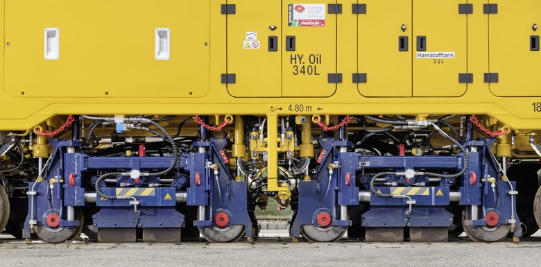
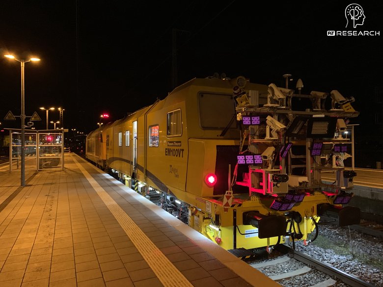
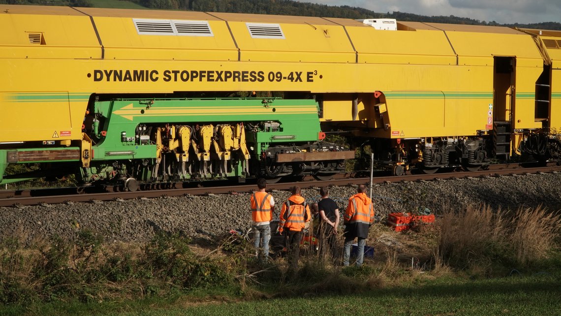
The TU Wien's Institute of Geotechnics has been studying so-called machine-ground interaction systems for many years. These systems describe the interdependencies between machine and ground. After a successful joint research project on track tamping, Plasser & Theurer decided to collaborate with TU Wien once again. This time, the research focuses on the next step in the maintenance process: track stabilisation. Experts use field surveys performed in the Open Rail Lab of Austrian Federal Railways (ÖBB) to investigate the interaction between DTS, track panel, and ballast.
Influence from below
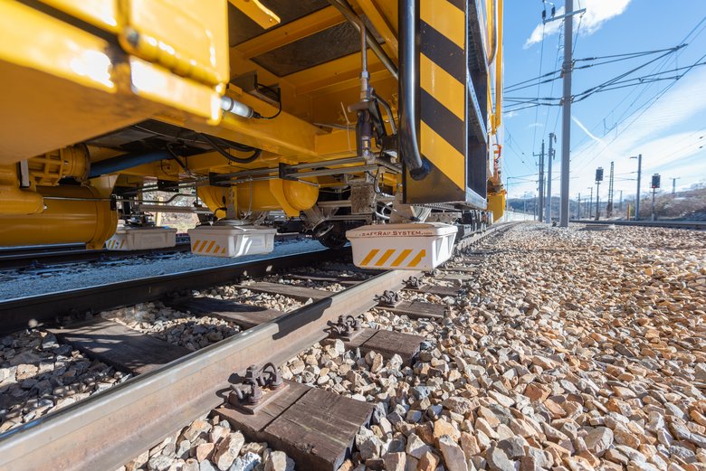
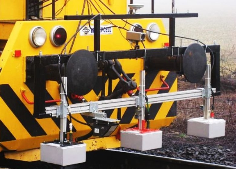
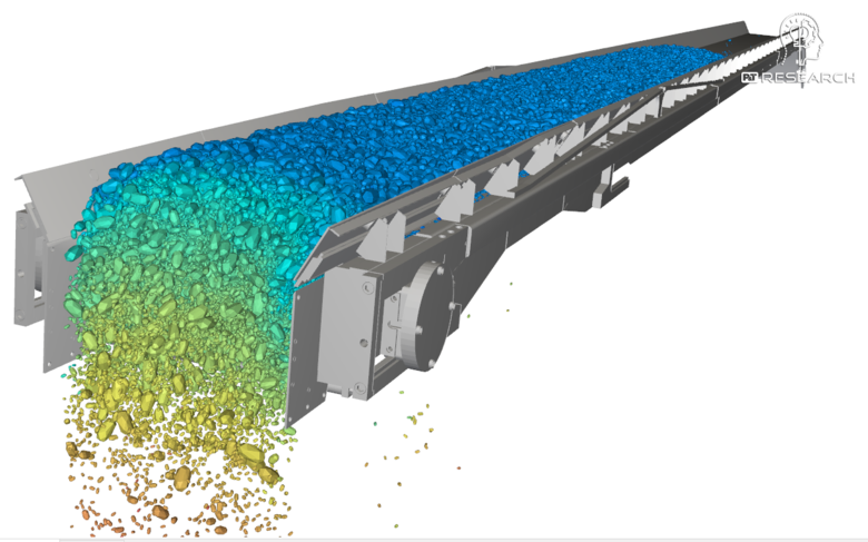
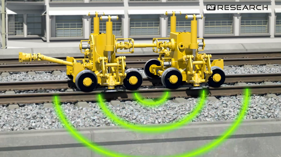
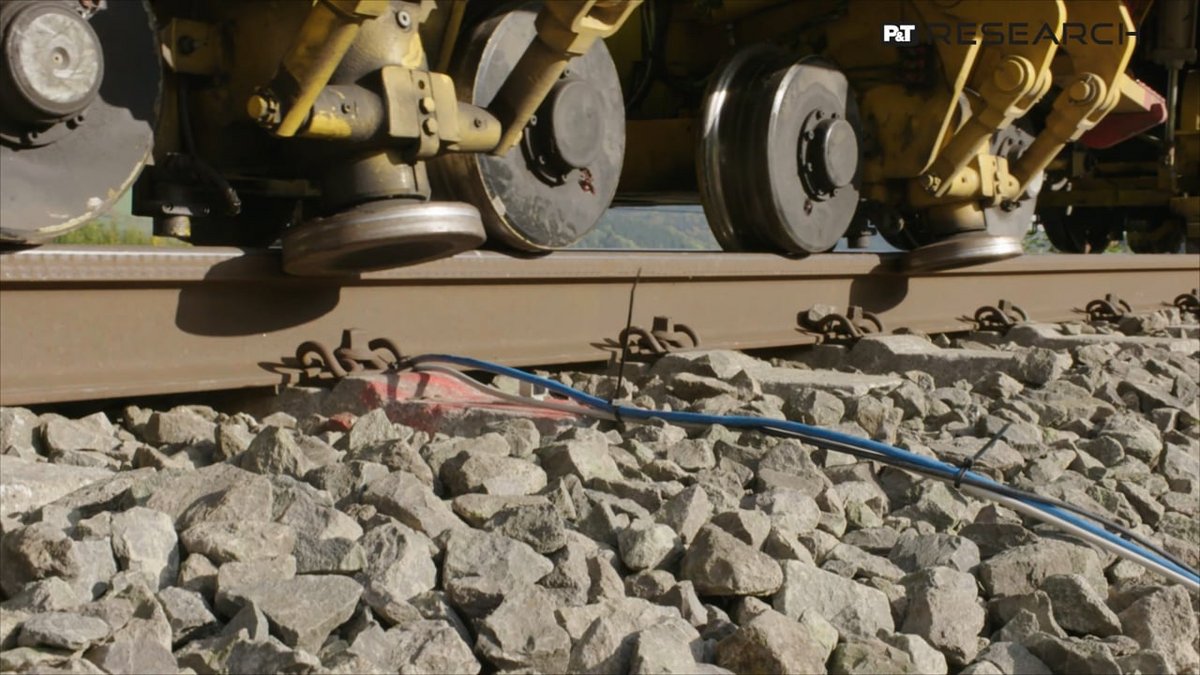
When the process parameters (e.g. excitation frequency, load, and amplitude of the imbalance excitation) remain constant, changes in movement behaviour are expected to translate into changes in the degree of ballast compaction. In the future, these changes in movement behaviour could serve to determine the degree of ballast compaction and lateral track resistance. The degree of ballast compaction influences movement behaviour. Sleeper type, rail fastenings, cross-section type of the ballast track, and the subsoil are also potentially significant factors. The test setup accounted for the influence of these factors: it included three sections of track with varying types of sleeper and rail fastenings, as well as varying subsoil and ballast conditions. Three-dimensional acceleration sensors installed on the DTS and on one sleeper per section of track helped to measure the movement behaviour.
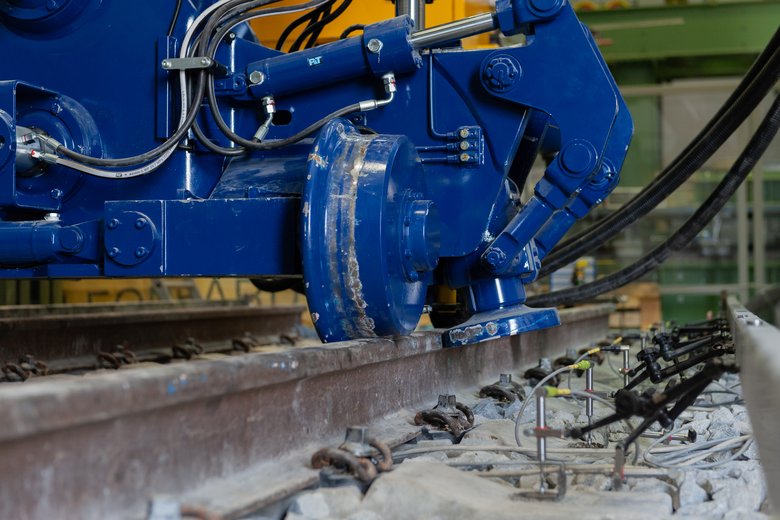
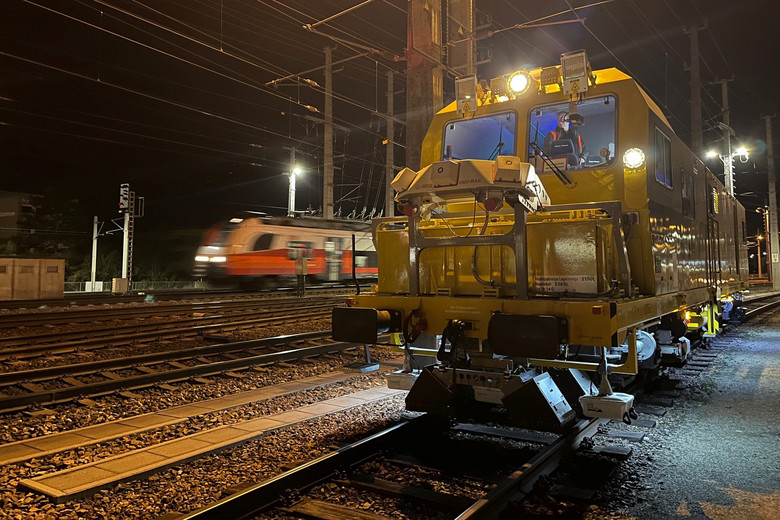
The first experiment was a free vibration test. Its aim was to obtain information about the vibration behaviour of the DTS and its uninfluenced movement behaviour. The test involved lifting the DTS while exposing it to various frequencies and amplitudes. In the next step, the DTS performed several working passes along the respective test section. The process parameters remained unchanged; the only variable that changed was the degree of ballast compaction (e.g. by tamping before the test run). During measurements, the instrumented sleeper was exposed to varying excitation frequencies, amplitudes of the imbalance excitation, and loads. The aim was to learn more about the frequency dependence of the interaction system comprising DTS, track panel, and ballast.

![[Translate to Französisch:]](/fileadmin/_processed_/a/9/csm_202109_Visualisierung_beim_Stopfen__1__f0921ecd25.png "[Translate to Französisch:]")